4.1 Antenna separation 4.2 Height requirements 4.3 Antenna alignment 4.4 Radiation 4.5 Separation and free radiation 4.6 Line-of-sight connection 4.7 Get out of the control cabinet 4.8 Wall mounting
4.9 Mast mounting 4.10 Consider the protection class (IP) 4.11 Polarization 4.12 Use of mounting material
4.1 Antenna separation
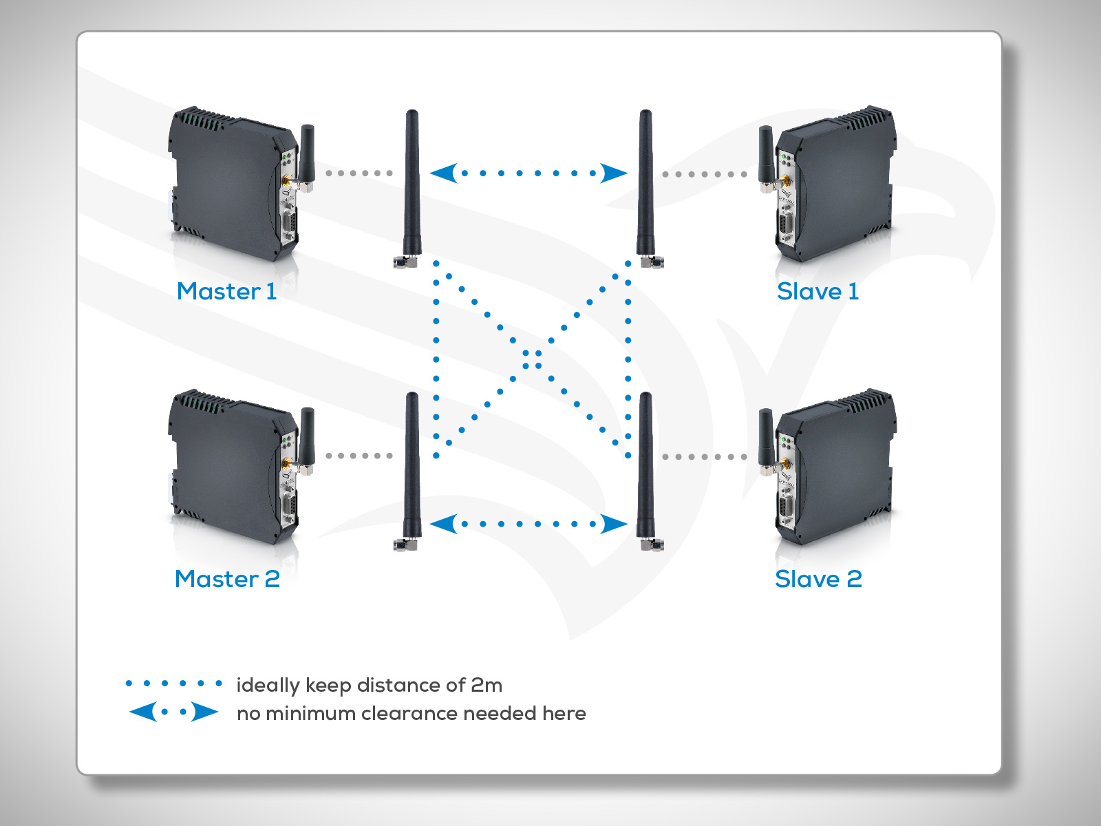
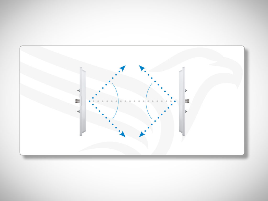
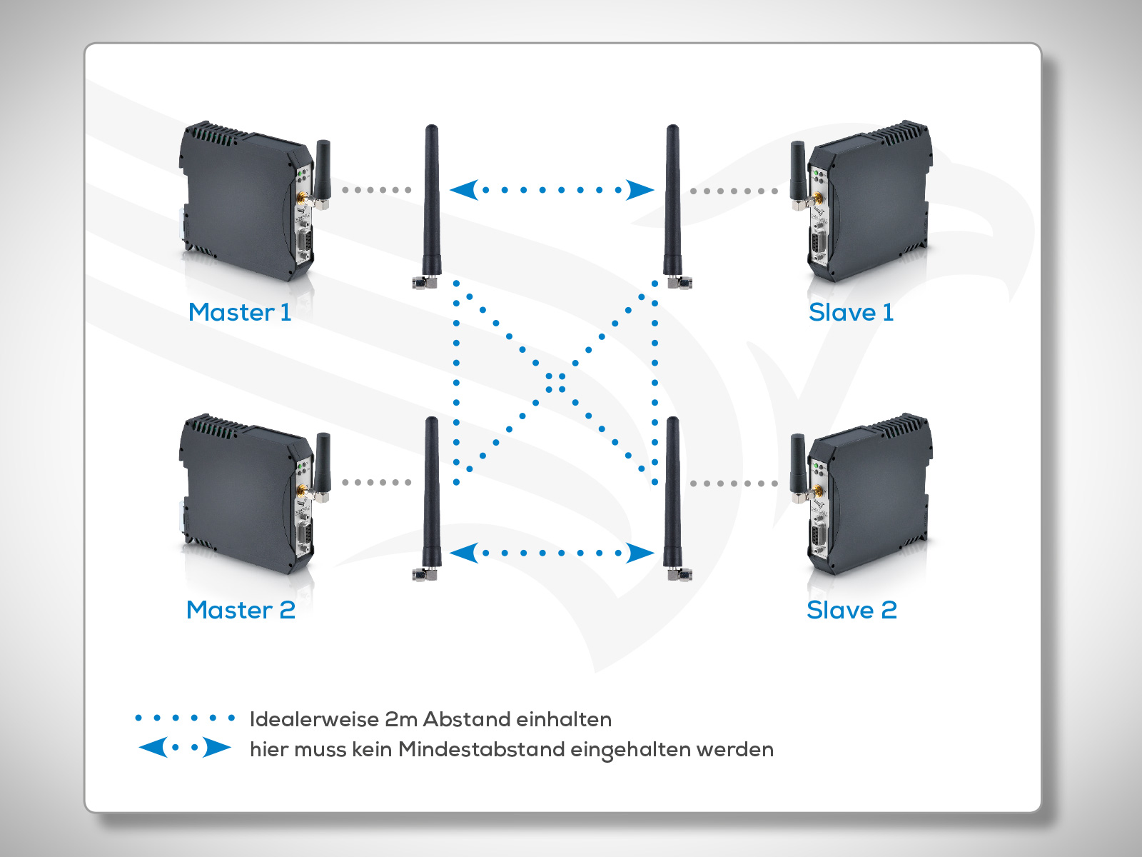
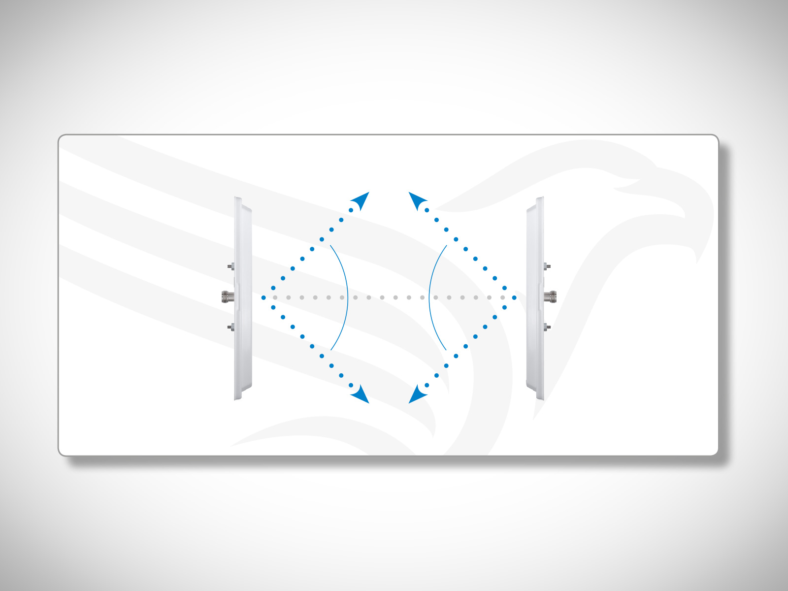
If you want to install multiple transmission paths in parallel the antennas should ideally be placed 2m apart. This minimum clearance does not apply to the distance between a sending and a receiving antenna. However, you have to keep in mind that the opening angles have to overlap (e.g. the ball antenna 10361). See also 4.4 Radiation.
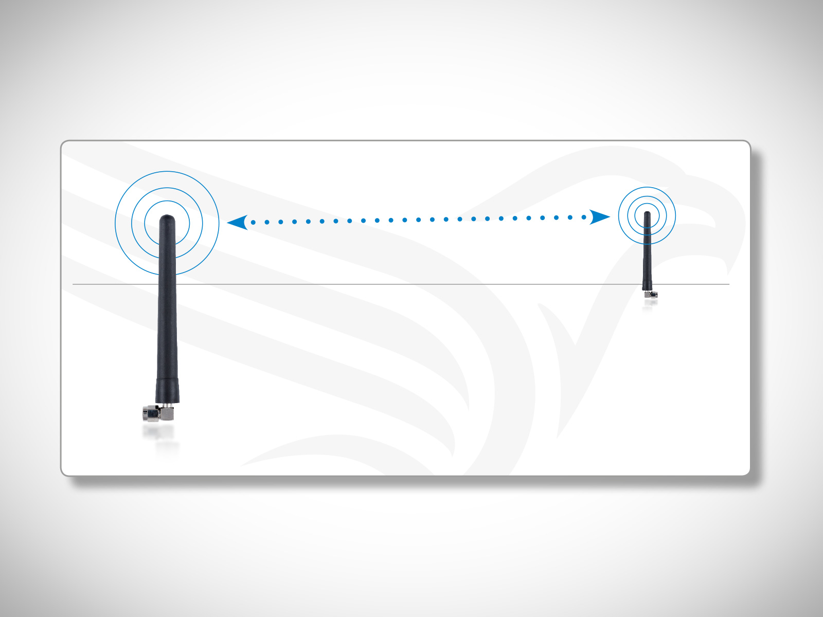
4.2 Height requirements
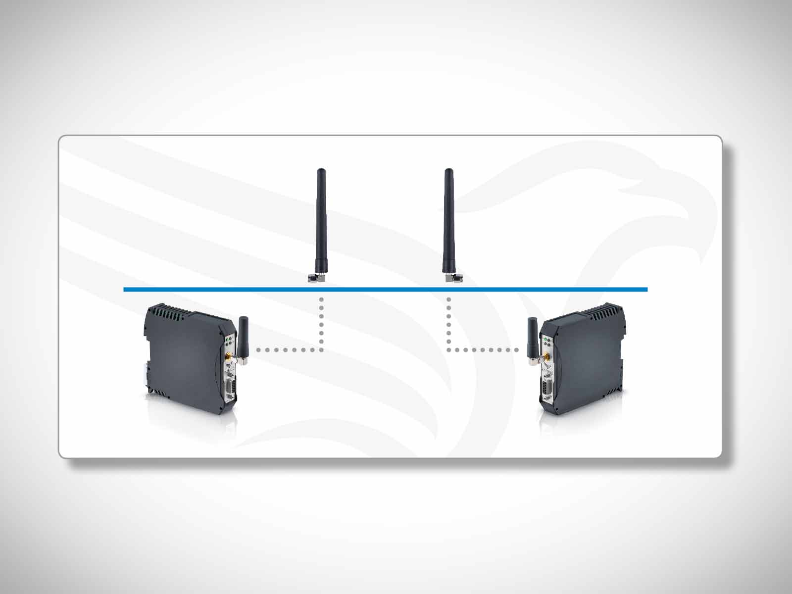
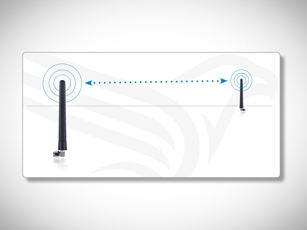
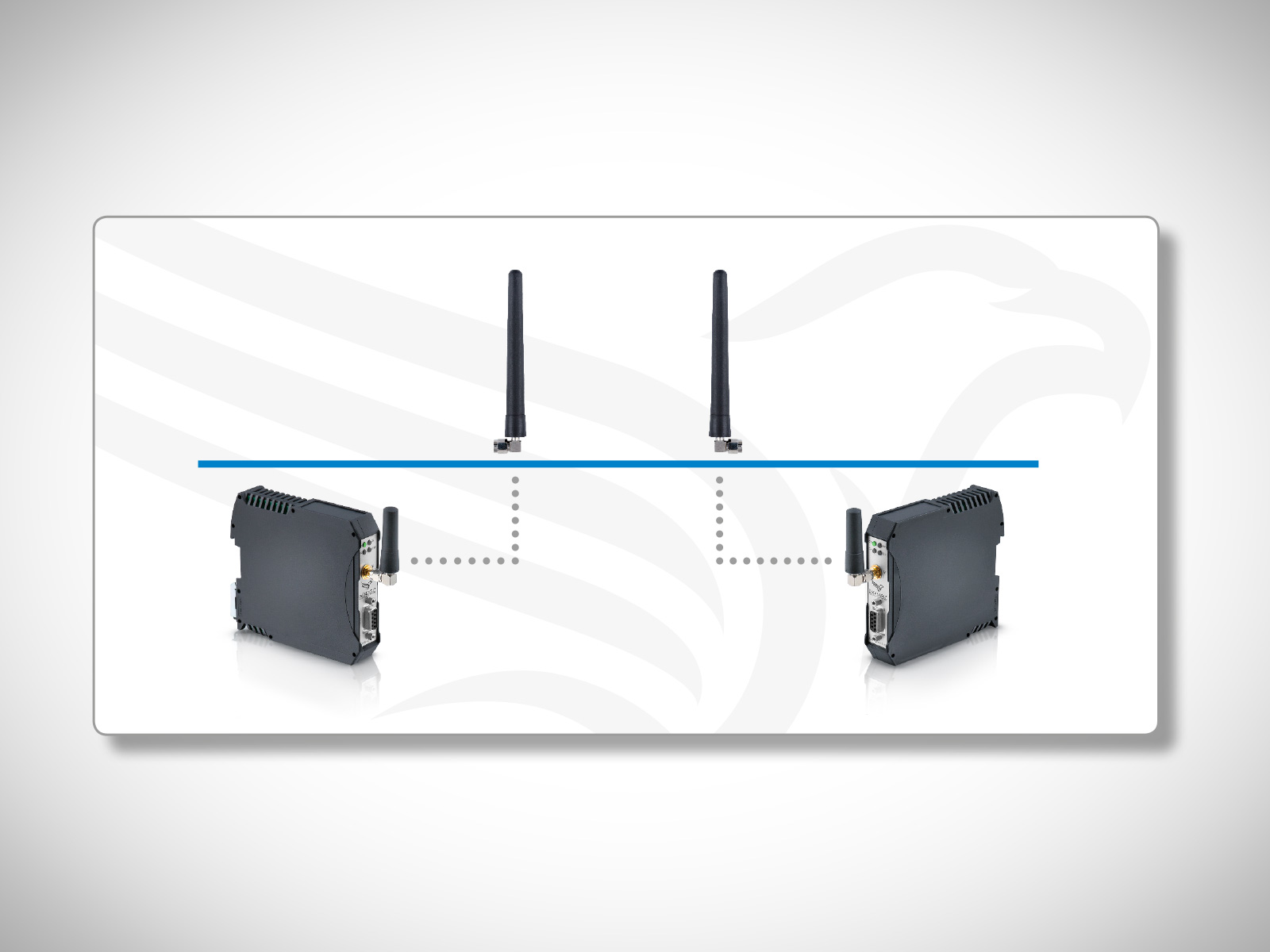
Antennas (without tilt) in a transmission path are to be placed at an appropriate height. The larger the opening angle, the larger the possible height offset.
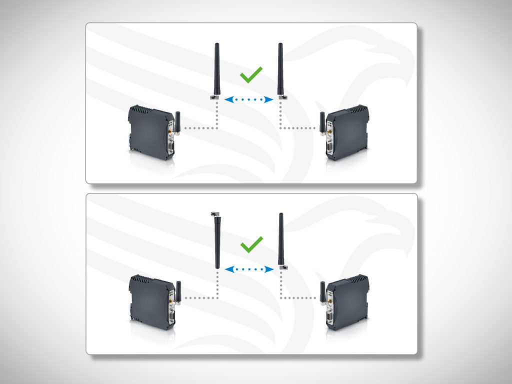
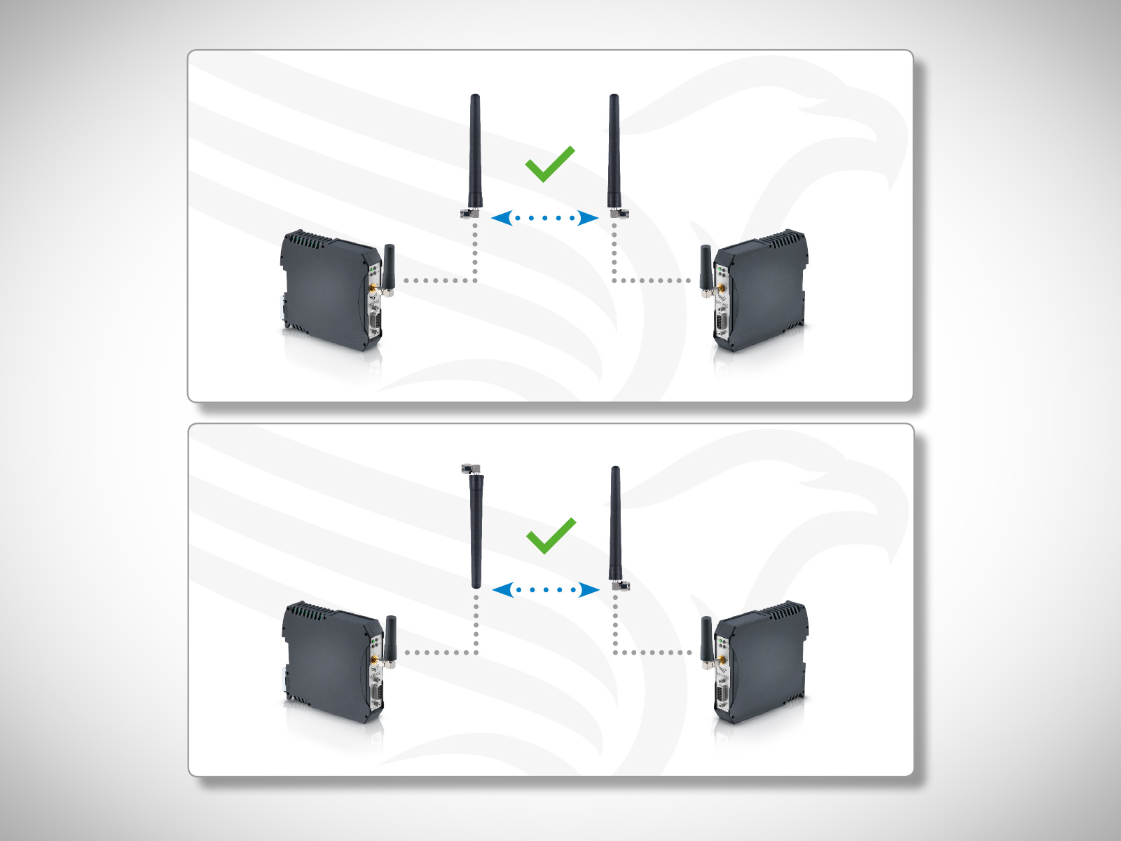
4.3 THE CORRECT ALIGNMENT FOR ANTENNA MOUNTING
Ideally, you need to direct the antennas in a transmission path in parallel to each other, e.g. all vertical.
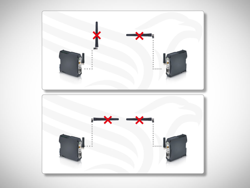
4.3 THE FALSE ALIGNMENT FOR ANTENNA MOUNTING
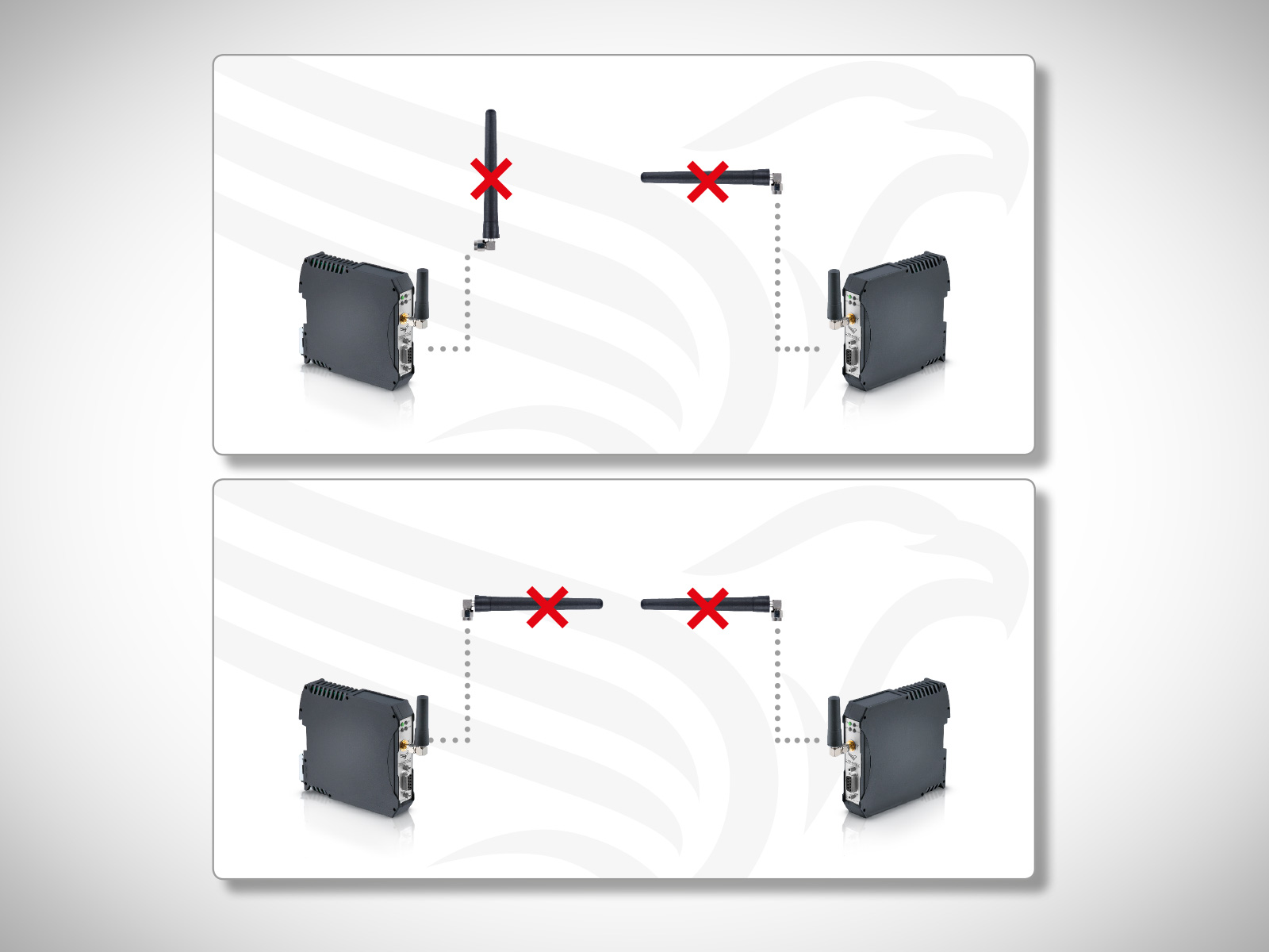
For antenna mounting, never mount with the head of an antenna facing each other (see also 2.2 The radiation characteristics of an antenna).
4.4 Radiation
When mounting antennas please be aware of their opening angles and the need for overlap.
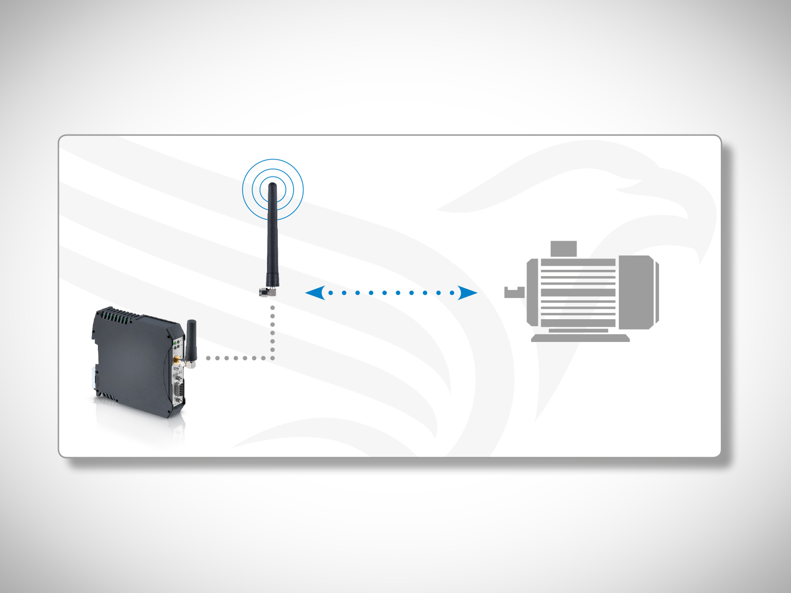
4.5 Separation and free radiation
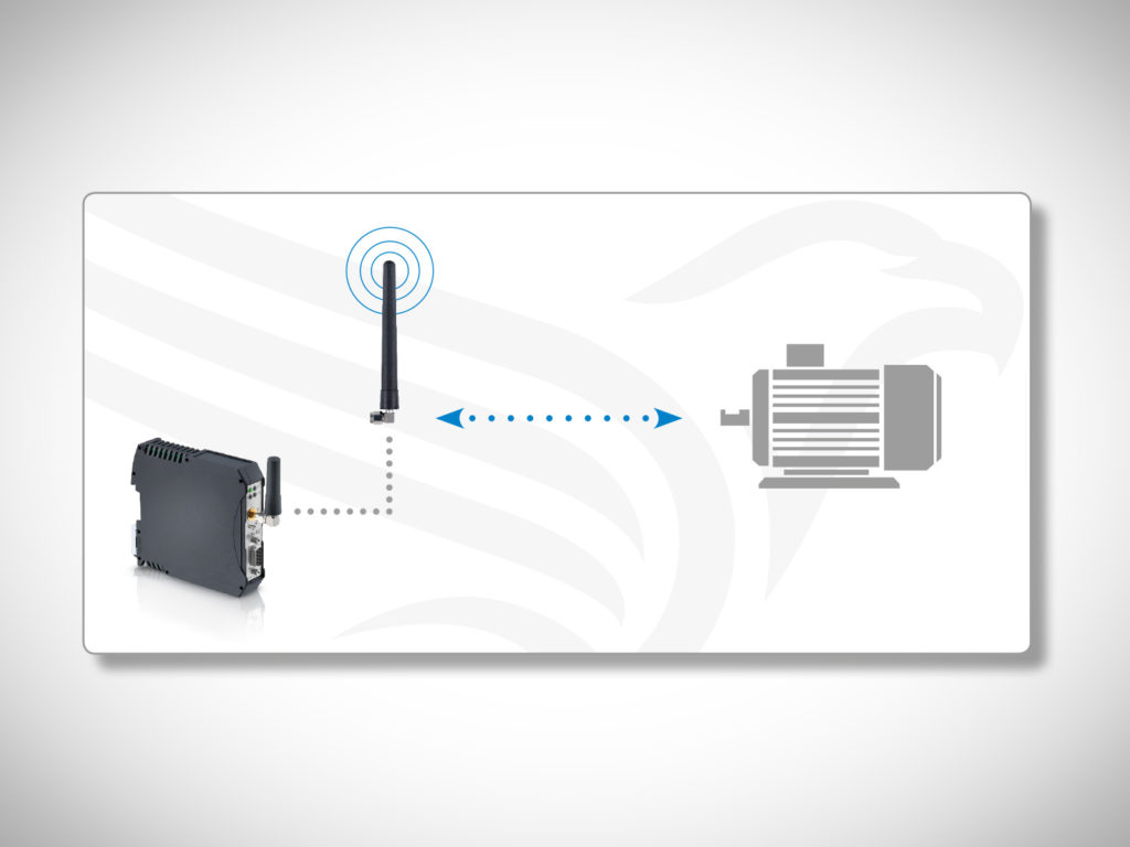
To avoid radiation disturbances and reflections do not install antennas close to metal parts, engines or frequency converters.
4.6 Line-of-sight connection
The antennas in a transmission path should have line-of-sight connection, to ensure optimal
data transfer quality (see 2.7 Fresnel zone).
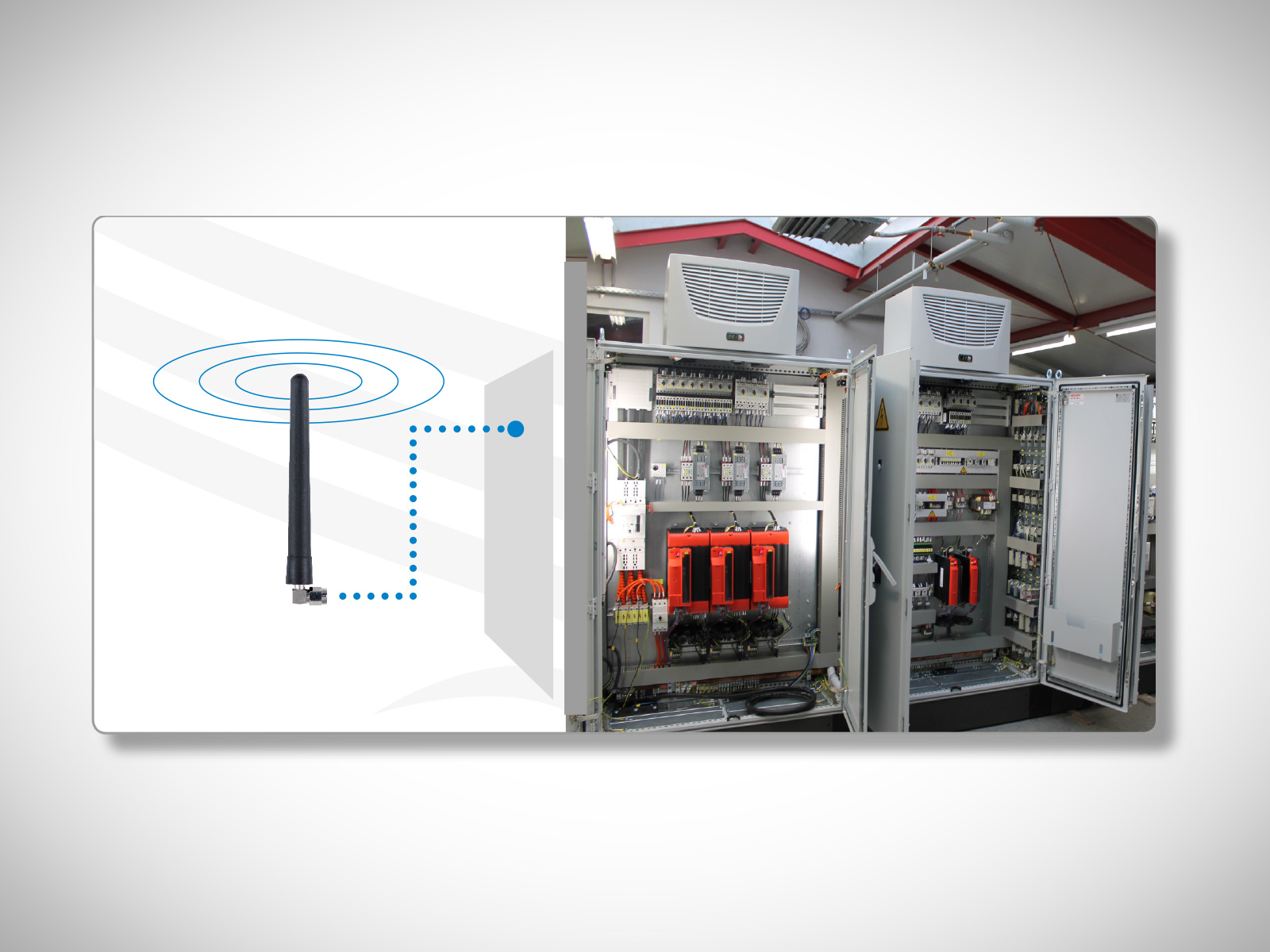
4.7 Get out of the control cabinet
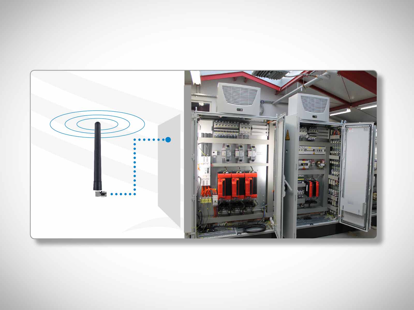
Please mount the antennas outside the control cabinet. If made of metal the cabinet causes a significant damping of the transmission signal, thus reducing transmission reach. If the control cabinet is made of synthetic material you can place the antenna inside the cabinet, as this material only has low impact on signal strength.
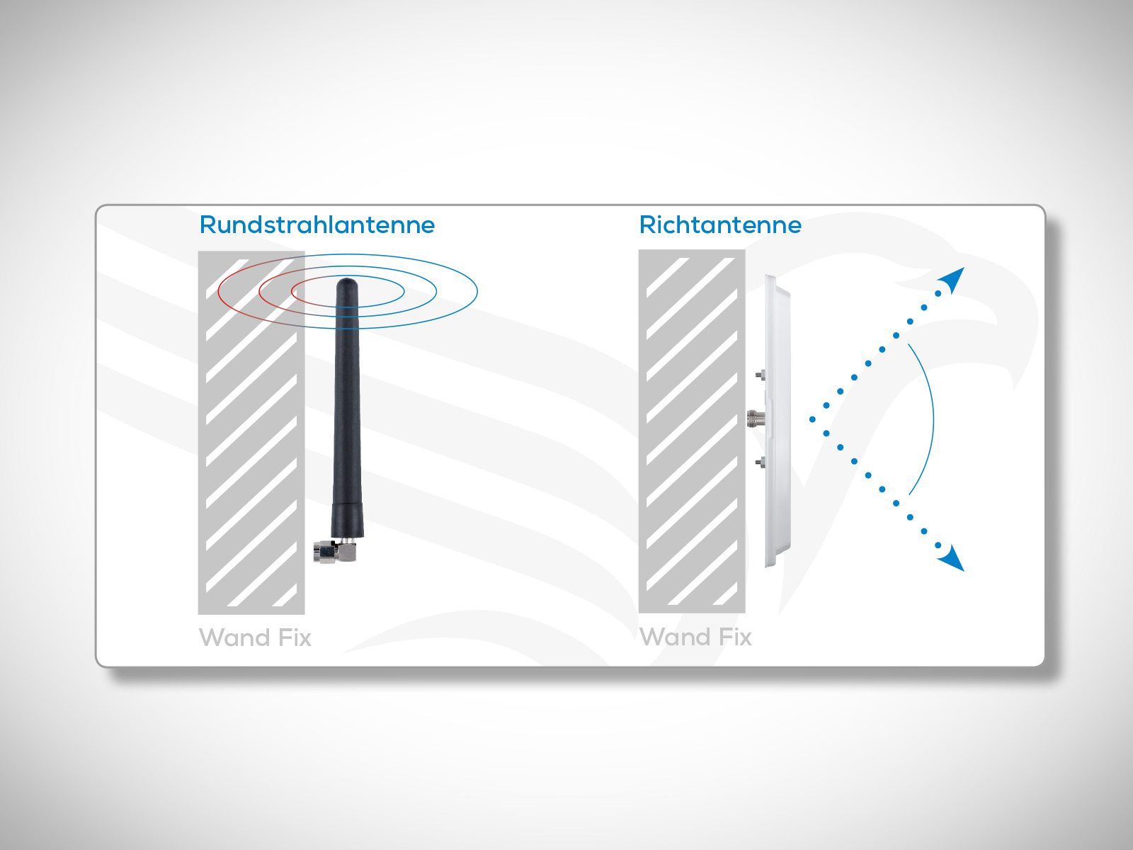
4.8 Wall mounting
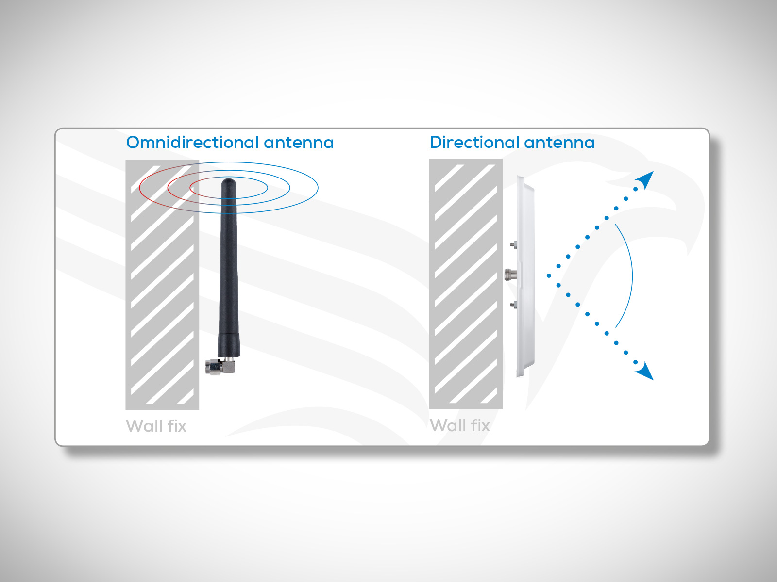
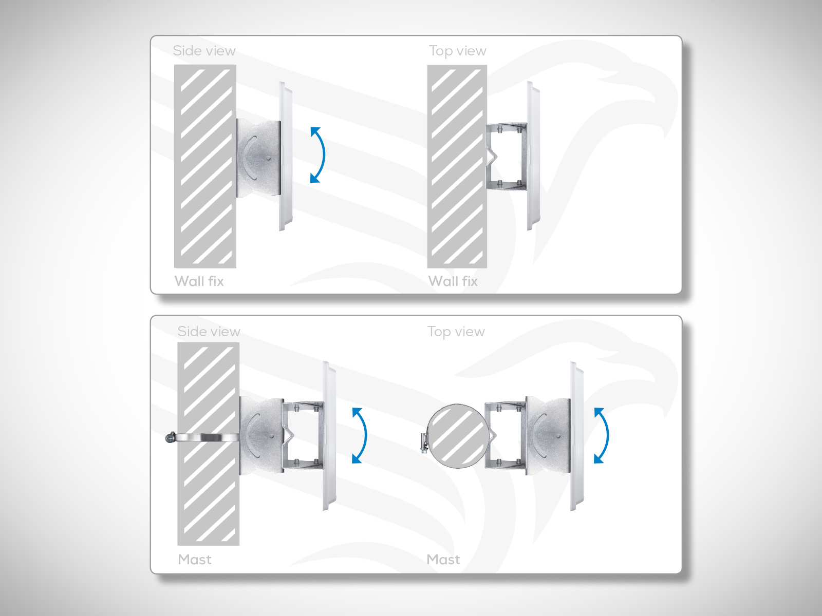
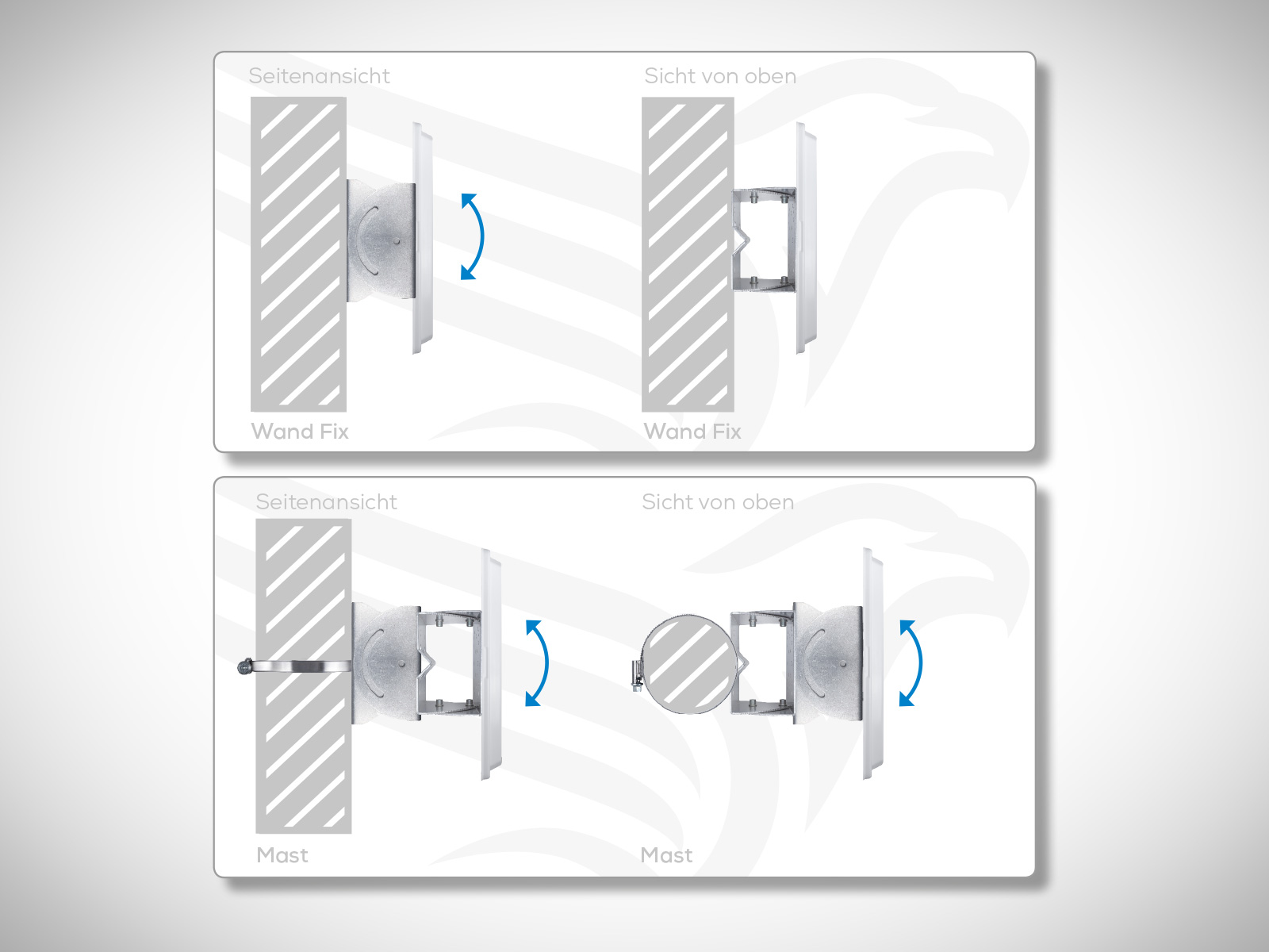
To achieve the best result mount directional antennas on a wall. If you request the characteristics of an omnidirectional antenna and if short reach is required you can wall mount an mnidirectional antenna as well. Wall mounted omnidirectional antennas cause reflections that reduce ransmission quality and reach.
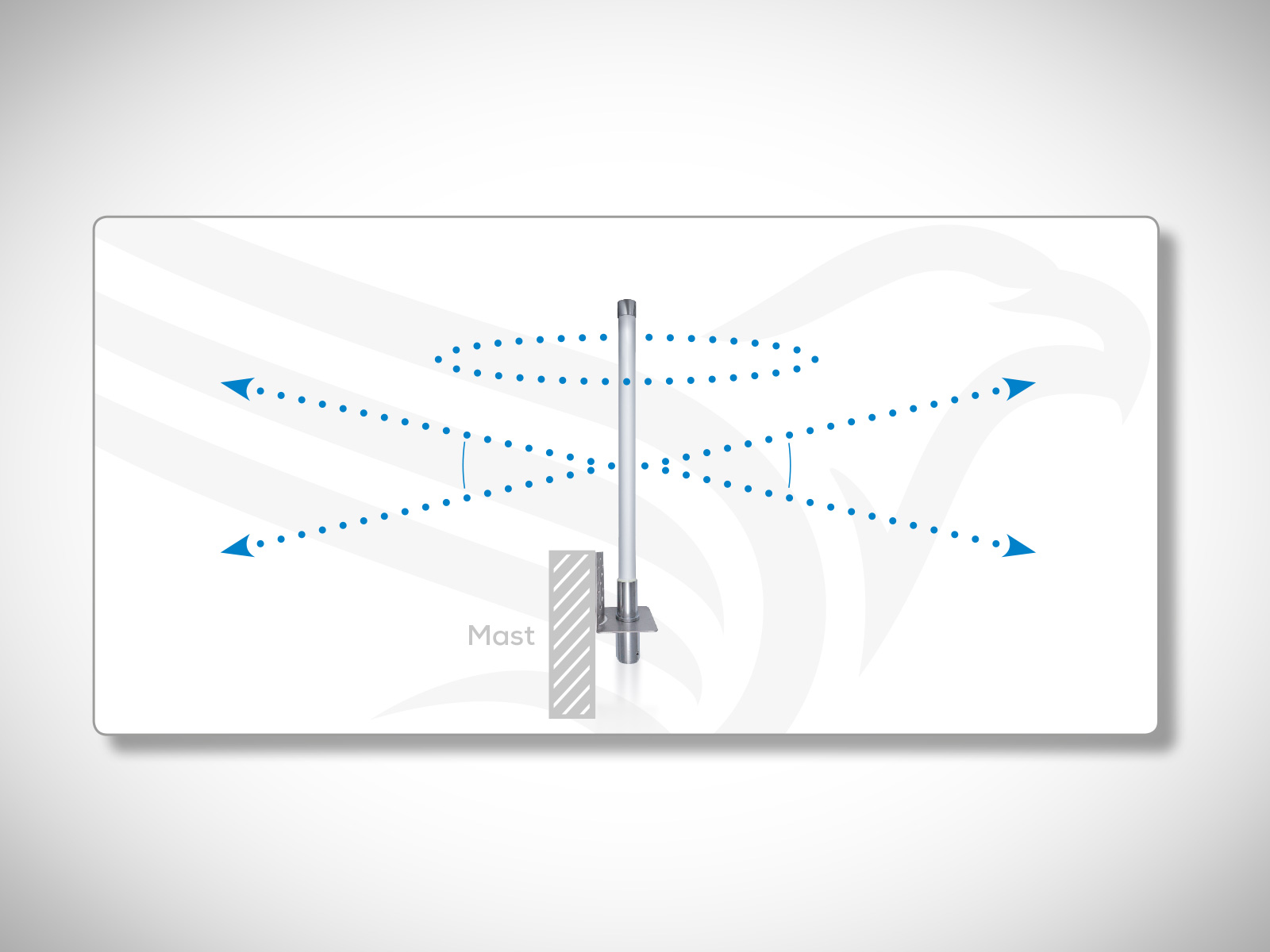
4.9 Mast mounting
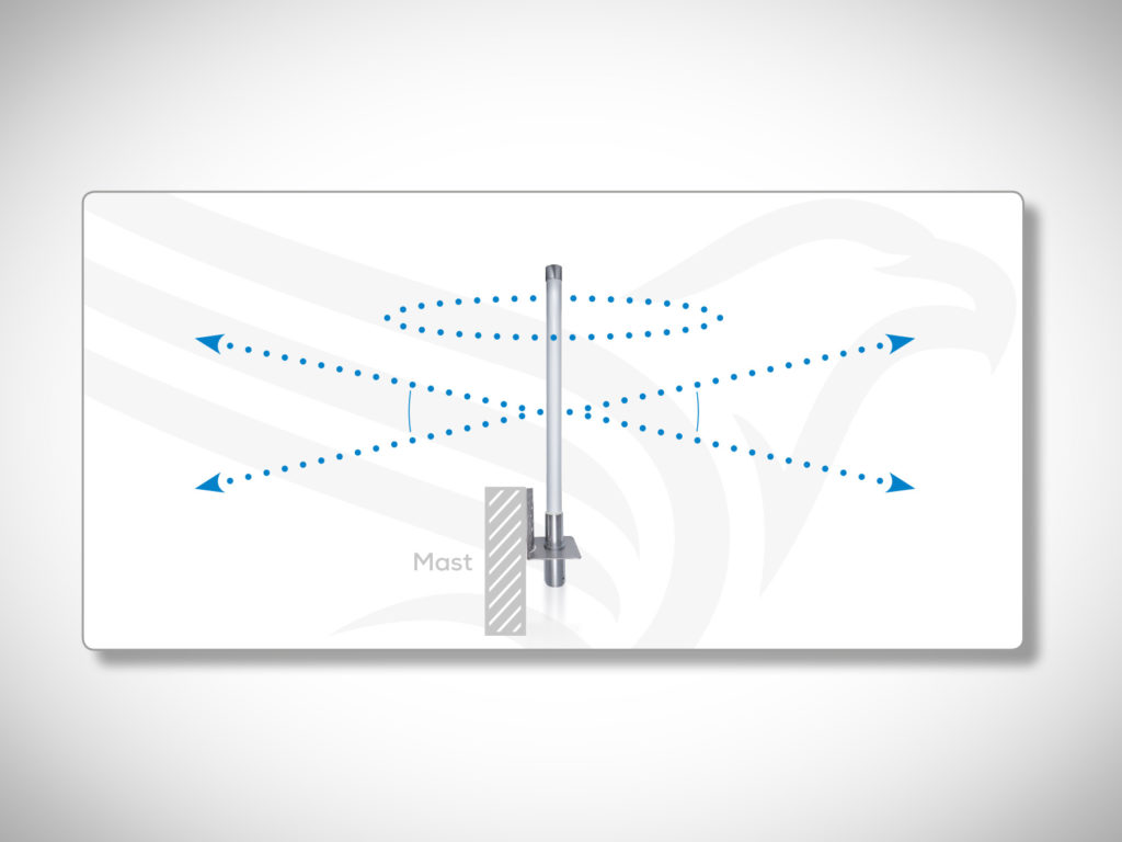
Ideally, choose a free standing mounting point for an omnidirectional antenna, e.g. on top of a mast, to achieve consistent horizontal radiation in all directions.
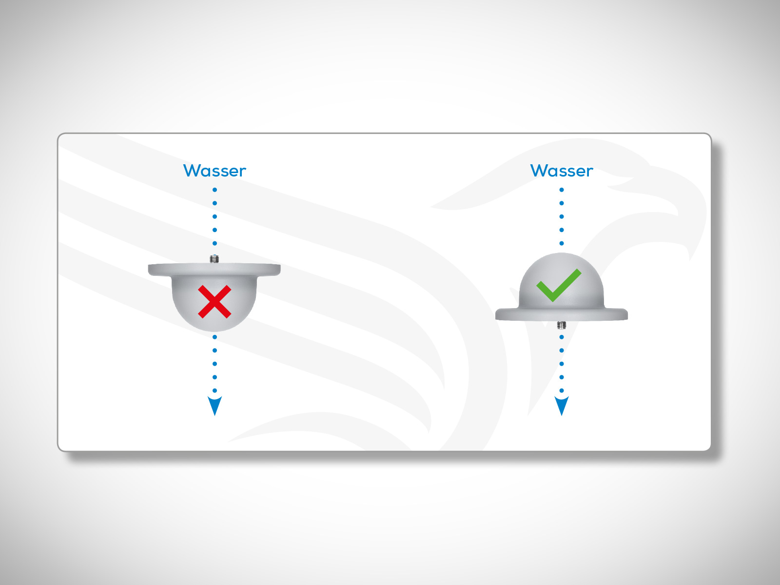
4.10 Consider the protection class (IP)
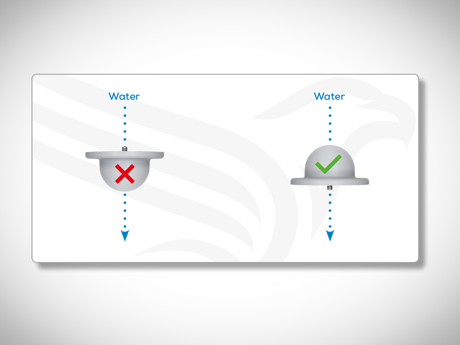
When you are installing outdoor antennas, please note that water must not be allowed to get inside the antenna. Furthermore you have to consider the protection class of the particular antenna you want to install.
4.11 Polarization
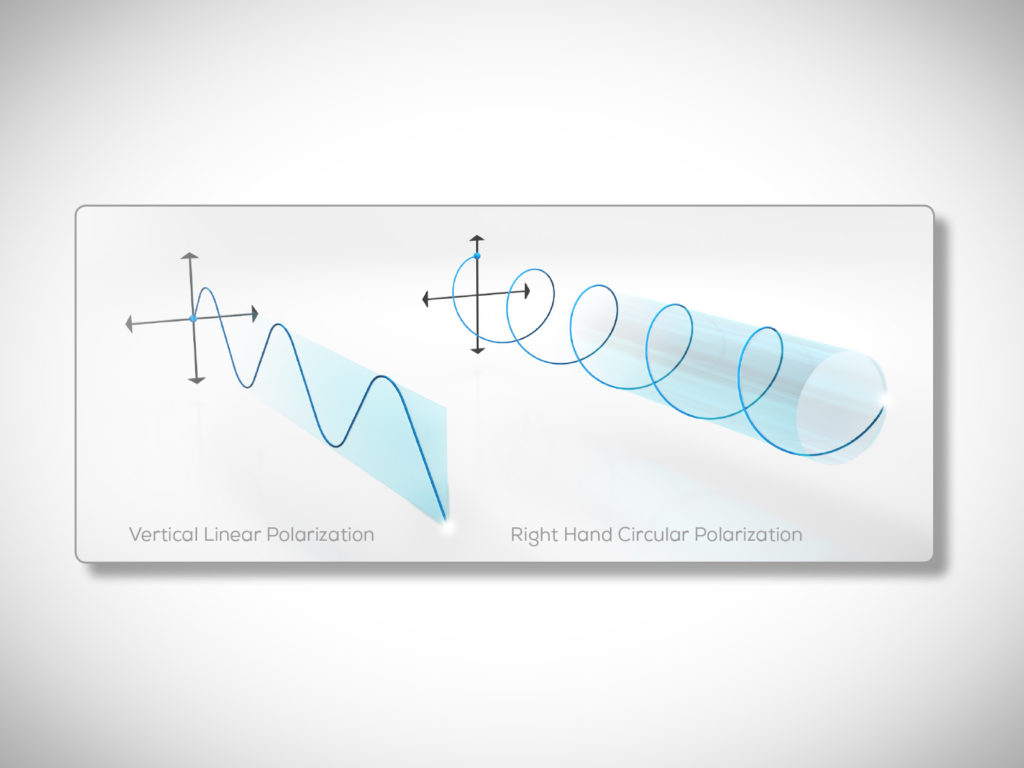
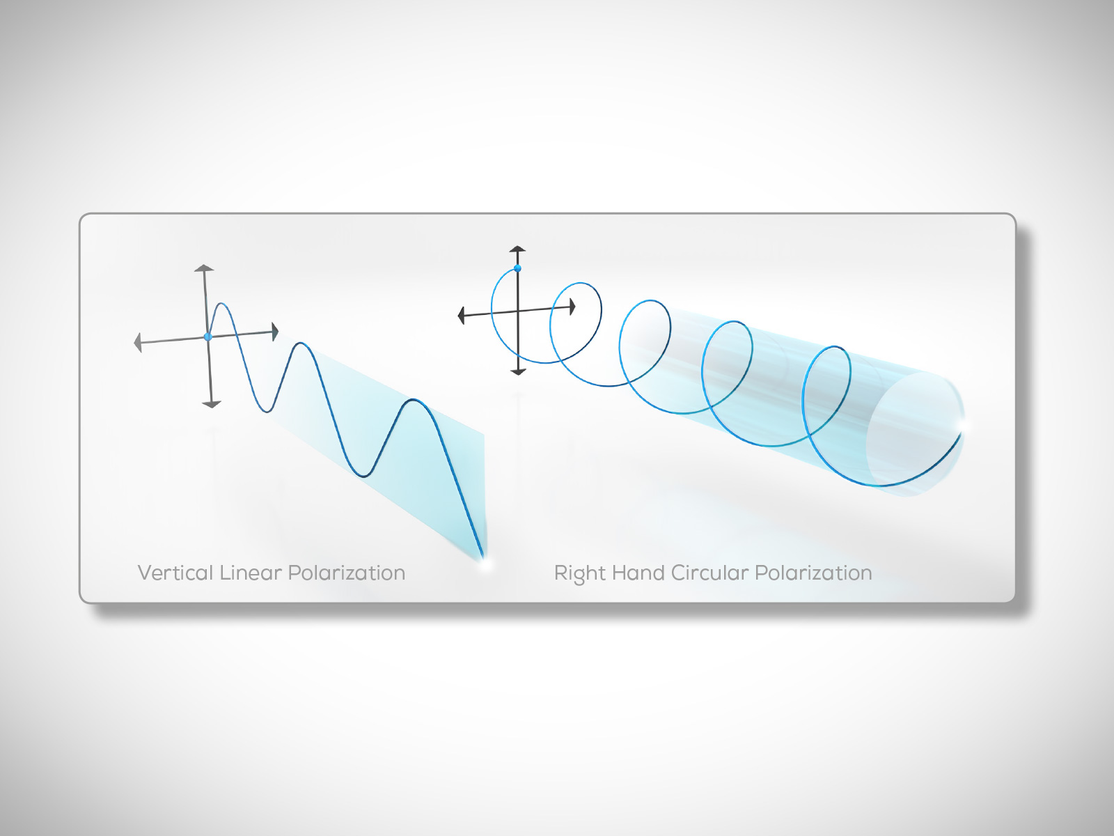
Antennas in a transmission path should ideally have similar polarization. Exception: For specific applications it can make sense to combine an antenna with a clockwise polarization – as a fixed station antenna – with a vertical polarizing antenna mounted on a mobile turning object.
Polarization explained:
Polarization indicates the directions of vibrations created by the electric field. It’s distinguished between horizontal and vertical linear polarization (VP), and right hand circular polarization (RHCP). The transmitting and the receiving antenna should have identical polarization. In case of unequally polarized antennas you can experience loss or no radio connection at all. We use antennas with vertical linear polarization (VP) or right hand circular polarization (RHCP). An RHCP antenna is suitable for directional radio communication with sight connection. For all other applications we recommend VP antennas.
4.12 Use of mounting material
Please use the mounting accessories offered by us, for the optimal positioning and orientation of directional antennas. The mounting materials match our antennas. By combining two mounting brackets (10519) you can pivot the antenna bilaterally.

Zubair Khan
If you have any questions about our products, please do not hesitate to contact me.


